Texas Willys Meet
This page last
modified April 13, 2005
You can find the rest of my web pages here
THE DANA MODEL 18 TRANSFER-CASE REBUILDING GUIDE
My name is Rick Stivers and writing this guide and my T-90 Rebuild Guide is about my
only claim to fame. I looked for detailed instructions for rebuilding the T-90
transmission in my truck. Unfortunatly, I couldn't find any, so with the help of some
friends at Willys Tech, I wrote my own
instructions. These instructions were so well received that I decided to write a set for
the Dana/Spicer Model 18 transfer-case. After I started this project, I discovered that
the repair manual's instructions for the transfer-case were adequate for the experienced
rebuilder. However, they left room for inexperienced people to commit errors. This
rebuild guide follows the basic instructions from the book with added steps and tips. I
also included instructions for removing the WARN Overdrive. This guide is divided into 4
sections, Disassembly, Inspection, Assembly and Troubleshooting. The sections are numbered
correspondingly. For simple instructions on how to change just the intermediate shaft, I
recommend a visit to Bruce Stanley's
page. His page inspired me to write the T-90 guide. In addition, here is a wonderful link
to David Hoelzeman's
web page. He is walking you through every stage of his Willys Pickup rebuild
including the Transfercase. If you have any questions or suggestions for improving
this guide please contact me.
IMPORTANT NOTICE AND DISCLAIMER
I am not a professional mechanic. I have gained my mechanical knowledge through trial
and error. I'm sure this guide has errors and I try to correct them as soon as they are
brought to my attention. Use it at your own risk. I wrote and posted it simply to pass on
to others what I have learned during my Willys experience. I will reiterate something
Bruce Stanley said on his page. There is no substitute for a good book. Buy the manual and
if you want to use the guide as supplemental info feel free to do so.
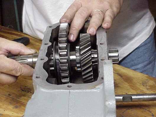
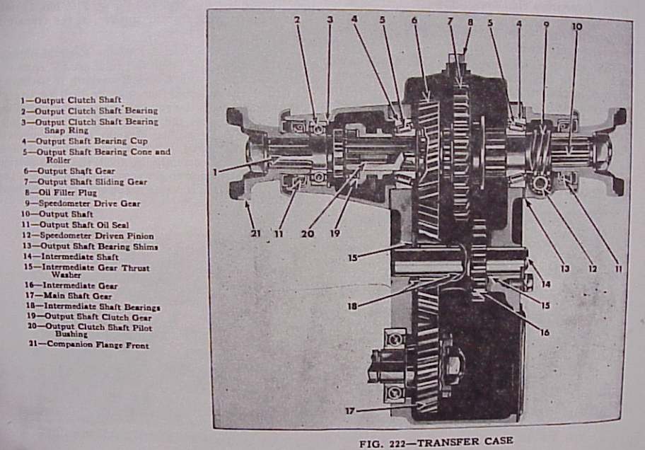
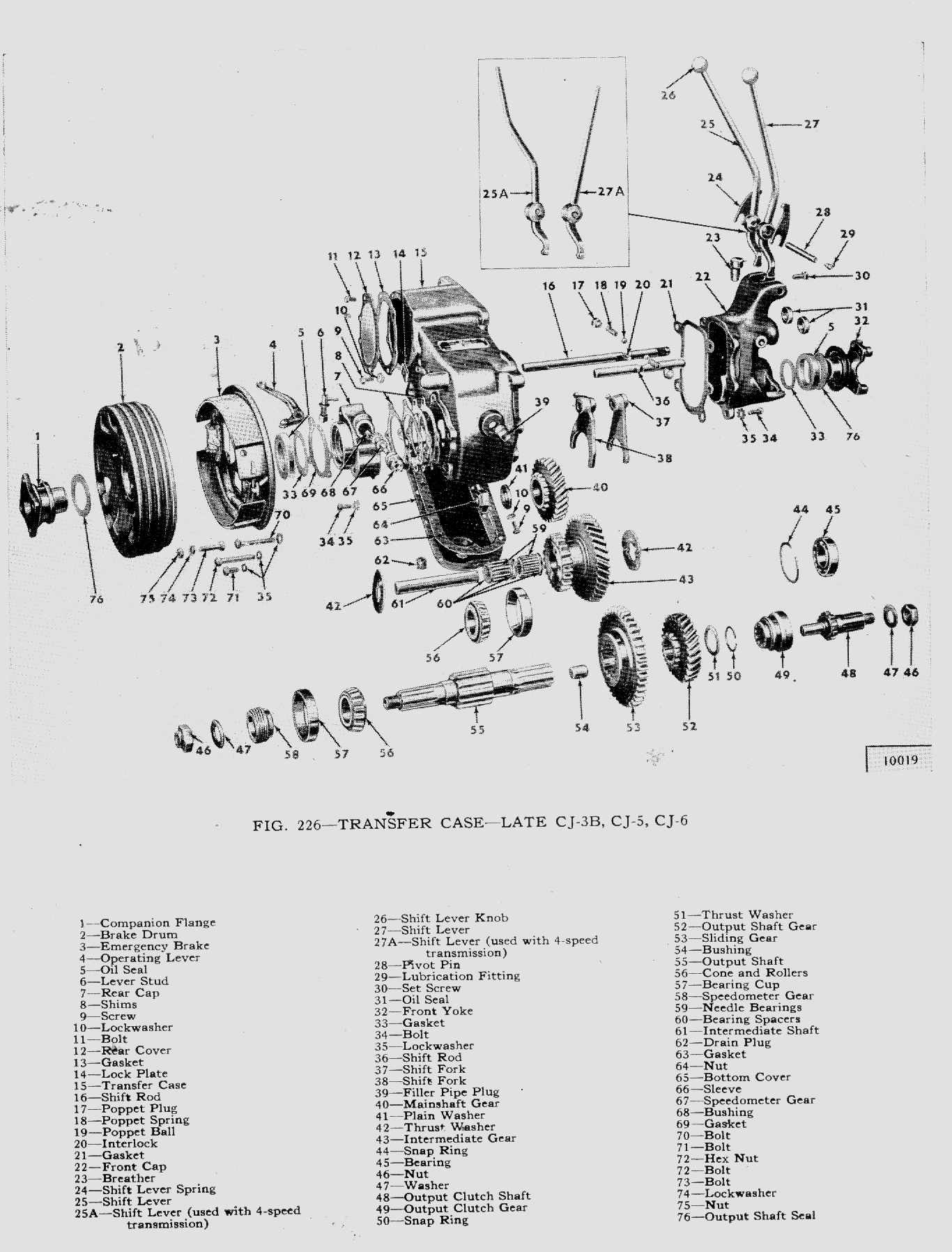
There is a cross-section picture of the transfer case assembly here, and the illustrated parts breakdown picture is here. These are huge files and is takes about 5
minutes to open each one. but I think they are suitable for printing as references.
This guide is a living document that is constantly updated with new suggestions and
comments. The T-90 guide has gotten a little sloppy with everyone's name added every time
they input a suggestion. I've decided to simplify things a little with this guide.
Whenever I add in a new suggestion, I will add a footnote giving credit to that person. I
may edit their text a little to keep the guide standardized but I will try to stay true to
their inputs.
Contributors:
(I know there were more people out there that contributed in the
early days but I don't have a record of who they are. If you want credit for your
contributions please contact me and tell me what part you contributed and I will add you
in.) The code following these names will be found directly after the section each person
contributed.
| Ron Smith * |
Jim Watson ** |
| Vern *** |
Alec Silitch **** |
| Ed Steinke # |
Bob Stewart #* |
|
|
Important Notice: Some
inferior intermediate shafts are being sold for the Model
18s. Here's how you can tell
if you have
a good one. Lay the shaft flat on a sturdy table. Place
a center punch on the shaft about 1/2" from the end. The surface in this area
should be as hard as the bearing surface yet doesn't need to be as smooth. Allow a 16oz
hammer to free fall onto the punch from about 10" high. If the punch leaves a
dimple in the shaft, it is too soft and should be returned to the supplier. A
hardened shaft will not be dimpled by the test and can safely be used. I tested 2
shafts with "Made in USA" stamped on them. They both failed the test, so
having that stamp does not guarantee quality. If you buy one of these inferior
shafts, please contact me so that I can determine who is selling them.
DISASSEMBLY
D1. Using a 1 1/8" or 1 1/4" * socket (Depending
on the nut installed) and a really big breaker bar, remove the nuts from the end of the
rear output yoke (companion flange for emergency brake equipped vehicles) and the front
yoke. To hold the yokes in place, the book calls for using Willys tool W-3281. Since this
tool is unavailable,, there are a couple of other options for removing the nuts.
D1a. Option 1 If the transfer case is still connected to the transmission. (This is the
recommended method if done in the vehicle)
D1a1. Put the transfer-case in 4 Wheel Drive Low.
D1a2, Remove the transmission shift tower.
D1a3. Shift the transmission into both first and third gear at the same time. Do this
by:
D1a3a. Moving the 1st/reverse sliding gear (That's the big sliding gear at
the back) as far forward as it will slide on the mainshaft.
D1a3b. And moving the clutch sleeve (that is the smooth sliding hub that the front
shifter fork goes into) all the way forward. This will lock the transmission and prevent
the yokes from turning.
Note: I do not recommend using
reverse gear because you could break the reverse idler boss off of the transmission
housing.
D1b. Option 2 If the transfer-case has been
separated from the transmission you must manually hold the yokes in place. Since the
transfer-case was too heavy and bulky to mount in my vise I used a large pipe wrench to
hold the yokes it in place. This can be very hard to do since the entire T-case will want
to rotate.
D1c. Option 3 If you are really industrious you could make your own yoke holding tool
from 1/4" plate steel or angle iron by drilling two holes in it to match the blot
holes in the yoke. Then you could bolt up to it to the yoke to hold it in place. Note: The
holding tool must not cover the nut you are trying to remove.
D1d. Option 4 (This is
the method I recommend if the T-case is out of the vehicle)
The last yoke nut I tried to remove beat all of the above listed
suggestions. After busting my knuckles and uttering words that should have melted the nut
off, I found an easier way to remove it. I took the T-case, along with my trusty 1
1/4" socket and dumped them in the back of my truck for a trip to a local tire shop.
Using my socket and their impact wrench, it only took them about 30 seconds to remove the
nut that I had spent 3 desperate hours trying to remove. They didn't charge me anything
but I tipped the man anyway. A little good will can go a long way toward
strengthening the comunity.
D2. Remove the front output shaft output yoke (use a wheel or hub puller if needed).
D3. If not equipped with the parking brake drum and brake assembly, proceed to step D4.
Remove the parking brake drum and brake assembly.
D3a. The companion flange nut has already been removed so all you need to do is slide
the brake drum off. You may need to use a wheel puller to remove the parking brake drum. 

D3b. Remove the four bolts that hold the brake assembly to the rear bearing cap. One
bolt is much shorter than the others because it only screws into the bearing cap and not
the case.
D3c. Loosen the nut on the emergency brake tensioner spring and slide the tensioner off
of the emergency brake lever.
D3d. Remove the emergency brake backing plate. The brake shoes can remain in place.
D3e. Remove the emergency brake lever from the rear bearing cap.
D4. If the transfer-case shifter arms are already removed proceed to step D5. If they
are still in place:
D4a. Shift the transfer-case into 4wd low.
D4b. Remove the lock-wire from square-headed set-bolt (Some have a countersunk Allen
style set bolt) on the inboard end of the shifter pivot-pin.
D4c. Remove square-headed set-bolt
D4d. Slip the pivot pin out the end with the grease fitting.
D4e. Remove the shifter arms
CAUTION: If the shifters are equipped with the anti rattle clips (And
they should be), they are spring loaded. Hold a rag around them while removing the shifter
arms to prevent the clips from flying out during removal.
D5. If the transfer-case is not equipped with a WARN OD proceed to step D6. If it does
have the OD, it must now be removed.
D5a. Shift OD into Neutral (This would be the space between the two detents on the
shift rail.
D5b. Disconnect the OD shifter linkage and remove it.
D5c. Remove the five rear case bolts with lock washers from the OD.
Note: Do not remove the end cap
bolts at this time. Remove only the five rear case bolts. If you see a large nut, do not
attempt to remove it because you have removed the wrong bolts. #
D5d. Slide the OD out of the transfer-case. If
it will not come out and it probably won't:
D5d1. Gently pry with a side to side motion using large bolt drivers under the edges of
the case. It may be necessary to rotate the OD housing to access pry points.
D5d2.
CAUTION: There is a thin-walled, long, flat oil tube that runs down the
inside of the OD. Make sure not to damage it.
D5d3. Be careful that the OD does not pop out and fall to the ground. I placed a large
towel under it to catch it if needed.
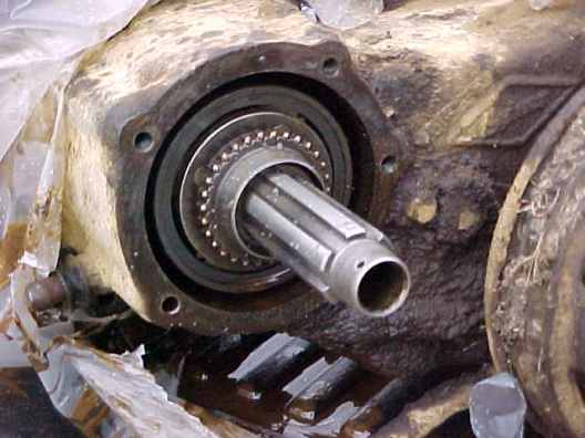
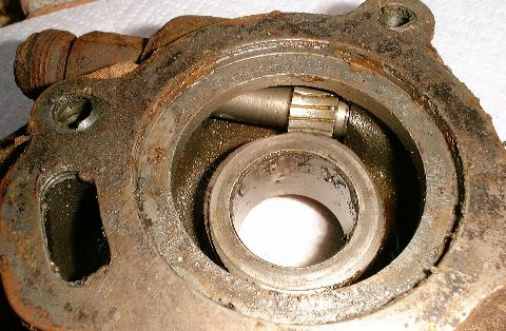
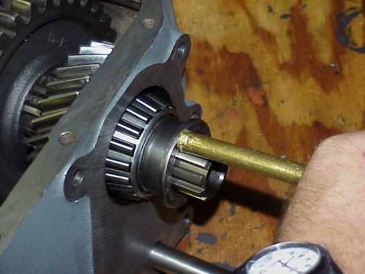
D5d3. If you remove the OD and see something that looks like this  , then you have made a mistake. Put everything back on and follow the instructions. That
shaft is supposed to come out with the OD. If you had left the large nut alone it couldn't
look like this. # I've been tempted to make a jig to fit on
the end of this shaft so a slide hammer could be used to pull the shaft but ODs are
expensive and I'd hate to mess one up. Note:
Here was an interesting case that was brought to my attention. It was so strange
that it took me a while to figure out what had happened. If you want to see it you
can go here.
By the way, Tim was successful in removing the OD
shaft. He said it only took him about 2 minutes once he understood how the OD
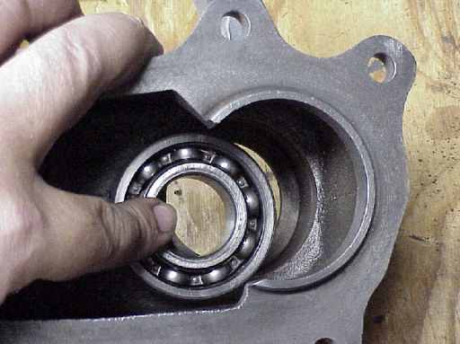
attached to the T-case. This is how the OD case side
should look when it is removed.
, then you have made a mistake. Put everything back on and follow the instructions. That
shaft is supposed to come out with the OD. If you had left the large nut alone it couldn't
look like this. # I've been tempted to make a jig to fit on
the end of this shaft so a slide hammer could be used to pull the shaft but ODs are
expensive and I'd hate to mess one up. Note:
Here was an interesting case that was brought to my attention. It was so strange
that it took me a while to figure out what had happened. If you want to see it you
can go here.
By the way, Tim was successful in removing the OD
shaft. He said it only took him about 2 minutes once he understood how the OD
attached to the T-case. This is how the OD case side
should look when it is removed.  And on the T-case side it should look like
this.
And on the T-case side it should look like
this. 
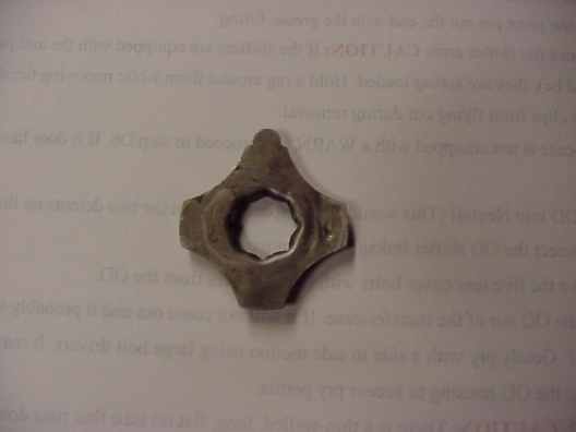
D5e. Remove the special locking clip from inside the planetary gear using a long pair
of needle nosed pliers. This can be done by grabbing the two little tabs on the clip and
squeezing them together.
D5f. You will see a special locking clip with an 8 pointed hole inside of it. Normally
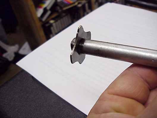
you can simply remove it with a set of snap ring pliers holing on the inside of it.  If not insert a 3/8" extension
into the star shaped hole in the locking plate and gently counterclockwise and then back
clockwise to free it up.
If not insert a 3/8" extension
into the star shaped hole in the locking plate and gently counterclockwise and then back
clockwise to free it up.  This shouldn't require more than about 1 or 2
degrees of motion either way. Once freed, it should easily slip out.
This shouldn't require more than about 1 or 2
degrees of motion either way. Once freed, it should easily slip out.
D5g. Perform all of step D1a.
D5h. Insert a 1/2" extension into the square hole in the planetary gear and turn
counterclockwise. This special nut should have been torqued to 100-120 foot pounds and it
should take considerable force to break this loose (Mine didn't).
D5i. Once it breaks loose you should be able to easily unscrew the planetary gear from
the transmission output shaft using the 1/2" extension.
D5j. Remove the 10 ten bolts with lock-washers from the bottom cover and remove the
cover. Proceed to step D8.
D6. Remove the 10 ten bolts with lock-washers from the bottom cover and remove the
cover.
D7. If the transmission and transfer-case are already separated proceed to step D10.
If they
are still connected it is time to separate them.
D7a. Remove the cotter pin, nut and washer.
D7b. If you have difficulty removing the nut perform all of step D1a. Once the nut and
washer are removed the main gear can be removed from the main shaft.
D7c. If the output gear sticks on the shaft two thin wooden wedges can be tapped in
between the rear bearing and output gear to pop it loose.)
D8.
If you do not plan
to rebuild the transmission, then this next step is critical.
D8a. Reinstall the two front transmission sifter tower bolts in the T-90 case.
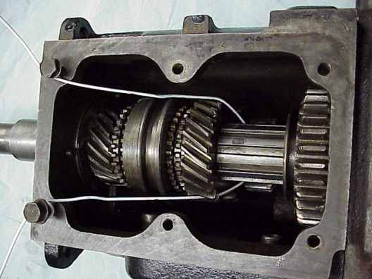
D8b. Loop a piece of wire around the T-90 mainshaft, directly behind the mainshaft
second speed gear and tightly secure each end of this wire to the two bolts.  If you do not do this, the transmission mainshaft
will slide backwards during the separation and the pilot bearings will fall to the bottom
of the transmission case. They can be retrieved and reinstalled, but it's much easier to
secure the gear.
If you do not do this, the transmission mainshaft
will slide backwards during the separation and the pilot bearings will fall to the bottom
of the transmission case. They can be retrieved and reinstalled, but it's much easier to
secure the gear.
D9. Cut the lock-wire and remove the five bolts and lock-washers holding the
transfer-case to the transmission.
Note:
One of the five bolts comes in from the transmission side instead of the T-case side.
Failure to remove this bolt will result in a broken case if too much force is applied. Separate the two cases.
D10. Remove the front yoke (Use a wheel puller if needed).
D11. Remove the intermediate shaft locking plate bolt and locking plate from the
backside of the case.
D12. Using a large brass drift, drive the intermediate shaft out from the front of the
transfer-case. You may be surprised at how much force you must use to drive this shaft
out. It took about 20 shots with a 3lb sledge to get it to start moving. Once it started
it was pretty easy.
CAUTION: You may be tempted to use a steel drift to drive this shaft
out. Don't do it. It can mushroom the head of the shaft making it even harder to get the
shaft out and possibly even damaging the case. NEXT CAUTION: Do not attempt
to drive the intermediate shaft out from the rear of the case. The shaft is 0.004"
larger on the rear than it is on the front. Driving it out from the rear can stretch the
front hole or even jamb the shaft in the hole. In addition, if the needle bearings aren't
worn out, you will be trying to flatten them into the gear's bearing surface. They could
ruin the gear.
D13. Remove the intermediate gear, bearings and thrust-washers from the case.
D14. Remove the spring caps from each side of the transfer-case shifter and remove the
springs and poppet balls. Some of these spring caps have a very short head and can be
difficult to get a socket to grab hold of. You can make the job easier by grinding down
the 1/16" shoulder on the front face of the socket. This will allow the socket sides
to grab fully on the cap.
D15. Shift the front wheel drive shift lever shaft into the engaged position. That will
be all the way forward.
D16. Remove the front bearing cap:
D16a. Remove the lock-wire from the five bolts
D16b. Remove the bolts holding the front bearing cap in place.
D16c. Remove the entire assemble as a unit. Note: The High/Low shift rod will stay in
the main case.
D16d. Tilt the bearing cap onto the side the high/low shift rod was removed from and
remove the interlock pin. Note the position of this pin between the two shift rods. It
prevents the t-case from being shifted into two-wheel low. The idea behind this was to
prevent too much power being applied to the rear drive train. Many people elect to remove
the interlock pin to obtain this function.
D17. If it was equipped with an emergency brake proceed to step D19 otherwise remove
the rear yoke.
D18. Remove the rear-bearing cap:
D18a. Remove the lock-wire from the four bolts
D18b. Remove the bolts and slide the cap from the shaft.
D19. Around the mainshaft you will find a large spiral shaped gear. This is the main
speedometer gear. Remove it.
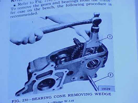
D20. Using a brass or rawhide hammer, drive the mainshaft output shaft to the rear of
the case until the rear bearing race is driven from the case.
D21. Drive the front bearing forward enough to use a set of flat-bladed snap ring
pliers to move the output shaft snap-ring forward, and out of the groove. On some T-cases
this bearing just slides forward but many others require force. The book calls for using
Willys Tool 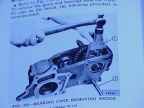 . I made my own
 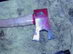 from a cheep steel hatchet, by cutting the middle
out of it with a grinder. It worked great.
from a cheep steel hatchet, by cutting the middle
out of it with a grinder. It worked great. 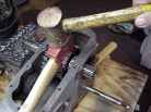 Once it was driven in between the gear and
the bearing I was able to gain more clearance by tapping on the side of the hatchet blade.
By using cheap (soft) steel, it is less likely to damage the hardened steel shaft or
bearing.
Once it was driven in between the gear and
the bearing I was able to gain more clearance by tapping on the side of the hatchet blade.
By using cheap (soft) steel, it is less likely to damage the hardened steel shaft or
bearing.
Caution: Failure to
move this snap ring out of the groove has resulted in people cracking their cases. The
snap ring can not be seen until you drive the bearing forward on the shaft and this can
not be done by using a press on the end of the shaft.
D22. Once the snap ring is out of its groove, drive the output shaft out the back of
the case. 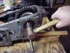
D23. Remove the rear bearing from the output shaft by either holding onto the bearing
while tapping the shaft against a board or by holding the bearing while tapping the shaft
with your mallet or brass hammer.
D24. Remove the sliding gear, output-shaft thrust-washer, snap ring and front bearing
from the case.
D25. Remove the lock-wire from the High/Low shift fork locking bolt (Some of these have
an Allen wrench set-bolt without lock-wire instead) and remove the bolt.
D26. Slide the High/Low shift rod from the case.
D27. Drive the front bearing race into the case and remove it.
D28. On the rear-bearing cap, remove the secondary speedometer gear by unbolting the
sleeve from the cap and sliding the gear out.
D29. Remove the oil seal from the rear-bearing cap. I clamped my bearing cap into a
vise and used a large screwdriver to pry the seal from the cap. With more reflection on
this I think a claw-hammer would have worked better
. Note: I have since purchased a seal puller for $7 and it works very
well.
D30. Remove the front wheel drive shift fork, output clutch gear, and shift rod from
the front main bearing cap.
D31 Remove the clutch shaft from the front bearing cap.
D32. Remove the lock-wire from the shift fork set-bolt (Some of these have an Allen
wrench set-bolt without lock-wire instead). Remove set-bolt and slide fork from the rod.
D33. Remove the front-bearing cap snap-ring from inside front bearing cap. This snap
ring can be pretty intimidating at first to remove. There is a cutout in the cap at the 12
o'clock position. I found that by rotating the snap ring opening to the 3 o'clock
position, I was able to insert a screwdriver into the cutout and lever the spring clip out
with very little effort. The hardest part was rotating the snap ring.
D34. Drive the front roller bearing out from the front of the main-bearing cap.
D35. Remove the transfer-case vent.
D36. Remove the front main-bearing seal. This sounds pretty easy but there's a catch.
Behind the front main bearing seal is a support ledge for the bearing to set against. If
you are not careful you can get that ledge instead of the seal and break it off. I've seen
a number of them like that.
D37. Remove the shift rode seals.
There are two parts that I have not removed at this time. I do not feel that they
should be remove unless they are found to be defective. The speedometer gear bushing and
the mainshaft bushing.
INSPECTION
I spent 3 days cleaning the parts of this transfer-case. I recommend taking the parts
to a machine shop and having them dipped and cleaned. This would have saved a lot of time
kept the mess out of the house. I was surprised at how much carbon buildup there was on
the parts and how much effort was required to get it off. Note: I have rebuilt 7 T-cases
now and I have taken the last 5 to have them cleaned. I has cost me $20 each time but I
would have spent that much in cleaners anyway.
I1. Case:
I1a. Inspect the case for cracks and stripped threads.
I1b. Use a tap to clean all the threaded holes in the case.  Pay particular attention to the blind holes for the
inspection cover. Most of the dirt will come out in the tap relief grooves, the rest can
be blown out with compressed air. Wear eye protection. Failure to clean out the holes
could cause the case to break at the blind hole when the bolts are installed and cause
leakage.**
Pay particular attention to the blind holes for the
inspection cover. Most of the dirt will come out in the tap relief grooves, the rest can
be blown out with compressed air. Wear eye protection. Failure to clean out the holes
could cause the case to break at the blind hole when the bolts are installed and cause
leakage.**
I1c. Check mating surfaces for scratches, burs and gouges that could cause leakage or
improper fit. Lay a straight edge on all mating surfaces to check for warping. Use 220
grit sandpaper on a mirror or on a piece of glass to check for flatness.* (From this point forward I will refer to this procedure as
"Check for true mating surfaces.")
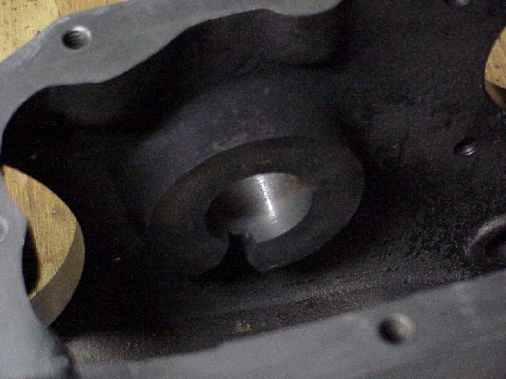
I1d. Inspect the inside edges of the intermediate gear journal for cracks and gouges. 
I1e. Each time the bolts are tightened in the case the metal around the edge of the
holes tends to put out just a little. Using the method described in I1c you can determine
the high spots. Use a file to carefully dress down those areas so they are flush. *** In the photo the shiny spots were the high spots that I've
dressed down. 
I1f. At this point I usually paint the case. I mask all areas and openings I do not
want painted. I have found that high temperature gray paint works very nicely on these
cases. It tends to give them a bit of an industrial or commercial look.
Alternative paint method: Before painting the
case, rub a thin coat of grease on surfaces you don’t want paint on, such as mating
surfaces and shaft holes. Paint will not stick to greasy surfaces so these areas can be
wiped off with a cloth after the paint has dried. This trick also works on gauge faces
when painting the dash panel. **
I1g. Insure all debris is removed from the case.
Do not forget to inspect the inside of the casement for the end of the High/Low shifter
rod for debris. I do a final rinse using brake cleaner in all the holes before I start the
final assembly
I2. Rear Output Yoke:
I2a. Inspect the shaft for a groove. The seal cuts this groove as the flange
turns. If the groove is too deep there are a few options.
I2a1. Using 220 and then 400 grit sandpaper carefully sand the yoke shaft in a
continuous cycle around the yoke. If you are careful you may be able to reuse your shaft.
I2a2. Install a stainless steel or chrome repair sleeve over the shaft to eliminate the
groove. The only company I've found that sells this sleeve is Speedi Sleeve Part # 99156
and it sells for about $34.
I2a3. Replace the output yoke with a new one. Carefully inspect the new yoke, as some
of the new yokes on the market are not drilled symmetrically. One set of holes will be as
much as 1/2" off from where the other set is drilled. This shouldn't make too much
difference on a front yoke because if its slower speed in 4 wheel drive but on a rear yoke
it could lead to bad vibration.
I2a4. Weld the groove to add metal and machine the surface back to specification. This
is a costly process and should only be done if you already have the equipment to do it or
a replacement part cannot be found.
I2b. Check the new seal of a solid fit on the yoke shaft prior to installation. I
recommend not using the single lip seals that are included in most T-case rebuild kits.
Let's face it, these seals aren't very good on new shafts and will almost certainly leak
on an old shaft. I recommend you replace them with National Federal Mogul oil seal Part #
473229. This seal is thinner than the original seal, but it has two sealing lips instead
of one. I recommend putting a spacer behind it to correctly position the seal on the
shaft. I used two old snap rings under my new seals to space them forward.
I2c. Inspect for cracks and twisting.
I2d. Check for true mating surfaces.
I3. Rear Bearing Cap:
I3a. Inspect the rear bearing cap assembly for cracks.
I3b. Check for true mating surfaces.
I3c. Check fit of secondary speedometer gear in bushing. There should be very little
play if any.
I3d. On models with emergency brake assemblies inspect the emergency brake lever stud
boss. This is a common area for breakage.
I4. Rear Bearing Cap Shims: Inspect shims for cracks or tears. A new shim kit
should be purchased but old shims can be reused if they are in good shape.
I5. Rear Cover: Inspect for cracks or rust and repaint as needed. This will not
be needed on T-cases with OD or PTO.
I6. Intermediate Shaft Lock-Plate: Inspect for cracks, bends and dents.
I7. High/Low Shift Rod: Inspect for cracks, rust and burs that could prevent it
from operating properly. Mine had a rather substantial bur on the interlock pin notch
where someone had tried to force it past the interlock. This was easily removed using a
file.
I8. Interlock Pin: If you plan to reinstall it you should inspect it for damage.
Both ends should be symmetrically rounded with now rust or burs and it should slide easily
in its hole.
I9. Front Bearing Cap Assembly:
I9a. Inspect for cracks.
I9b. Check for true mating surfaces.
I9c. Inspect the poppet ball and spring plug threads on each side for damage.
I9d. Inspect the shift rod holes to insure they are clear of rust and debris.
I9e. Inspect the T-case vent hole to insure it is clear
I9f. Inspect the front roller bearing hole for burs.
I9g. Inspect the front roller bearing snap ring groove for cracks.
I9h. Inspect all of the oil seal holes for burs or cracks. If seen a lot of front
bearing caps with the front main seal backing support broken off.
I9j. Paint as needed
I10. Transfer-Case Breather: (vent) Inspect to ensure that it is clear of
obstructions. Mud Daubers seem to like these a lot. If it has a Mud Dauber nest in it, you
aren't likely to get it clean with break cleaner. Soak it in hot soapy water for about and
hour and blow it out with compressed air.
I11. Shift Lever Springs: (anti rattle clips) Inspect for cracks or tears. I've
never seen one of these go bad but I've seen a lot of them missing. I usually paint them
and put them back on.
I12. Four-Wheel-Drive Shift Lever:
I12a. Inspect for proper fit on the pivot pin. Mine needed to be drilled out and a
bushing installed to prevent excess play.
I12b. Inspect where the square end fits into the shift rod. It should have freedom to
move but it shouldn't move around too much. The more it moves, the more slop you will have
in your shifter. You can weld up the ends and then grind them back down for a tighter fit.
If you do this make sure to sand the mating surfaces down smooth to prevent binding. In
addition the mating surfaces should be slightly curved to facilitate motion and prevent
binding.
I13.
High/Low Shift Lever:
I13a. Inspect for proper fit on the pivot pin. Mine needed to be drilled out and a
bushing installed to prevent excess play.
I13b. Inspect where the square end fits into the shift rod. It should have freedom to
move but it shouldn't move around too much. The more it moves, the more slop you will have
in your shifter. You can weld up the ends and then grind them back down for a tighter fit.
If you do this make sure to sand the mating surfaces down smooth to prevent binding. In
addition the mating surfaces should be slightly curved to facilitate motion and prevent
binding.
I14. Shifter Pivot Pin:
I14a. Inspect for excess wear or grooves.
I14b. Insure grease can travel freely through the pin. If you determine that you need a
new pin make sure to order a new grease fitting too.
I15. Front Yoke:
I15a. Inspect the shaft for a groove. The seal cuts this groove as the flange turns. If
the groove is too deep there are a few options. (See I2a, I2b, I2c, and I2d)
I15b. Check the new seal of a solid fit on the yoke shaft prior to installation. I
recommend not using the single lip seals that are included in most T-case rebuild kits.
Let's face it, these seals aren't very good on new shafts and will almost certainly leak
on an old shaft. I recommend you replace them with National Federal Mogul oil seal Part #
473229. This seal is thinner than the original seal, but it has two sealing lips instead
of one. I recommend putting a spacer behind it to correctly position the seal on the
shaft. I used two old snap rings under my new seals to space them forward.
I15c. Inspect for cracks and twisting.
I16. Both Shift Forks:
I16a. Inspect for excess wear of the pads. The pads of the shift fork should just
fit into the grooves in the gears. New parts have only 0.008" clearance when the fork
is installed in the groove. I do not recommend more than 0.012" clearance. My
four-wheel-drive shift fork was toast. The pads had worn about halfway through.
I16b. Insect shift forks for a snug fit on the shift rods. They should not wobble on
the rods.
I16c. Inspect the locking bolt hole threads for stripped or damaged threads.
I16d. Check for bends. The forks should come out from the shift rod at a 90-degree
angle. And the pads should be parallel to each other.
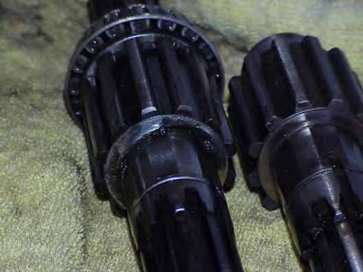
I17. Output Shaft:
I17a. Inspect for excess wear. Especially check the portion where the output-shaft gear
rides on it. If the vehicle has been towed with the transfer-case in neutral and the oil
level low, the output shaft gear will try to weld itself to the output shaft. Mine was
pretty well melted but it could still be turned.  The shaft on the left was mine and the shaft on the right is a output shaft from a
Model 20. Notice the difference in the surface area.
The shaft on the left was mine and the shaft on the right is a output shaft from a
Model 20. Notice the difference in the surface area.
I17b. Check the threads on the end of the shaft to make sure the nut screws on easily.
Many times these threads have been previously damaged by unthinking people with steel
hammers.
I17c. Inside the shaft is a brass bushing. Check to see how well it fits with the
output clutch shaft. There should be very little wobble. If the bushing is shot it should
be replaced. New bushings are available but must be reamed to fit your output clutch
shaft.
I17e. Make sure the output clutch gear, and sliding gears slide easily over the
mainshaft with no burs.
I18. Intermediate Gear:
I18a. Inspect for damaged, worn, chipped or pitted teeth.
I18b. Inspect the inside for excessive wear. If you can feel any type of ridge
inside, the bearing surface is shot. If the rest of the gear checks out, it can still be
used with a conical roller bearing kit.
I18c. Check the ends of the gear for gouges caused by debris in the case.
I19. Front Main Bearing:
I19a. Inspect for looseness or pits in the surface.
I19b. Does it howl, whistle or grind when spun? If so, it would be best to replace this
bearing but many people don't.
I20. Output Clutch Shaft:
I20A. Inspect for chipped teeth and cracks.
I20b. Is the end that fits the mainshaft bushing worn or damaged? Most are in good
shape unless they were damaged by rust. I did see one that Ron had where somebody left out
the front conical roller bearing and this part of his shaft was pretty badly worn, but
that shouldn't happen too often.
I20c. Does the nut screw easily on the threads. If not it's probably cheaper to replace
it than to fix it.
I21. Clutch Gear:
I21a. Inspect for chipped teeth and cracks. (There are two different gears
that can be installed here. Both fit but one should shift a little easier than the other
one.  .)*
.)*
I21b. Is the shift fork groove worn out or does the shift fork fit the gear well? As
stated earlier, there should not be more than about 0.012" of clearance in the
groove.
I21c. Does the gear slide easily over the output shaft?
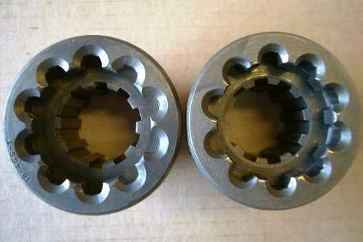
I22. Output Shaft Gear:
I22a. Inspect the end of the gear for oil and towing related damage. Mine
was cooked. It should have looked like the
replacement gear.
It should have looked like the
replacement gear. 
I22b. It should spin freely on the output shaft but not wobble excessively.
I22c. Inspect it for damaged teeth.
I23. Sliding Gear:
I23a. Inspect to insure that it will slide easily on the output shaft and
not wobble.
I23b. The shift fork groove should not be worn and the shift fork should fit snug but
not tight. As stated earlier, there should not be more than about 0.012" of clearance
in the groove.
I323c. Inspect the teeth for damage.
I24. Front and Rear Conical Roller Bearings and Bearing Cups:
I24a. Thoroughly clean these bearings until brake cleaner will spray
cleanly.
124b. Inspect for chips and nicks
I24c. Place clean bearings into their respective bearing cups. Push down firmly and
rotate bearings all the way around. If it isn't perfectly smooth, try cleaning them again.
If you can't get them to ride smoothly, they should be replaced. My bearings are in
excellent condition and I reused them.
I25. Primary And Secondary Speedometer Gears:
I25a. Inspect for damage. If properly installed and reasonably clean I don't
think they would be damaged. However, it has come to my attention that all of these gears
are not interchangeable with each other or ever with different bearing caps. We spent 20
minutes trying to fit a rear-bearing cap on a gear once that just would not fit without
forcing it. It was suggested we try installing the original gears and it worked fine. I
have seen the apparent results of mismatched gears and bearing caps. They looked like
this  and
this
and
this  .
.
I25b. Look for a bent shaft and make sure the secondary gear can easily rotate in the
bearing cap.
I26. Intermediate Shaft: The shaft inexpensive and should be replaced. They come
in three sizes 3/4", 1 1/8" and 1 1/4" make sure to get the right one.
I27. All of the other parts of the transfer-case should be replaced during a
rebuild. Make sure they send you the right needle bearings for the intermediate shaft you
are using. Make sure you parts kits include the following:
Intermediate-shaft needle-bearings and thrust washers
All gaskets
All seals
Poppet balls and springs
All snap rings
When I made statements in the text like, "shouldn't wobble excessively", or
"should slide easily", this is a judgement call on you part. I don't have any
exact tolerances for the fit. This means that if you are uncomfortable with the amount of
play that you have, then maybe you should go ahead and change the part.
ASSEMBLY
Before beginning assembly I recommend that you paint every surface that will be exposed
to the elements. Almost all of these parts are made of cast iron and they will rust. Does
that mean that if you don't paint them they will rust up and break? Probably not, but they
certainly will look much better when you cart them around town to show them off. I chose
machine gray high temperature paint for my engine, transmission and transfer case. I know
it's not original but it looks really good and shows anytime something starts to leak.
Frank Wood chose a cast iron gray spray paint from Eastwood that looks like bare cast
iron. It really looks great. Do not paint the mating surfaces of the parts. This will
cause leaks as the paint later separates from the metal.
When it comes to installation of the components I'm afraid the book is a little more
vague than helpful. For the most part it tells you to reverse the procedures. I've never
been very happy with that type of instruction so here we go.
Special Note: When I say to tap on something, I am referring to the use of a brass
hammer or rawhide mallet. Do not use a steel hammer to tap or beat on anything.
A1. Install the secondary speedometer gear into the rear-bearing cap.
A1a. Put a small amount of sealant on the treads of the sleeve before bolting it into
the bearing cap or it will leak later. Do not get any of the sealant on the speedometer
gear.
A1b. Ensure the speedometer gear turns freely.
A2.. Install the clutch shaft bearing (This is the ball bearing set, not the conical
bearing set) into the front bearing cap. 
A2a. Install the clutch shaft bearing retaining snap-ring in the cap.
A2b. Install it with the open end at the 3 o'clock position. Place the bottom half in
first and then lever the top half into the groove using a screwdriver wedged into the
cutout. 
A3. Install the output clutch shaft in the front main bearing with the threads pointed
toward the front of the cap. 
A4. Install the front-wheel-drive shift-fork on the front-wheel-drive shift rod (that's
the short rod*). The reinforcement boss on the fork should go
to the front of the transfer-case. The front of the shaft is the end with the square notch
cut for the shift lever.
A4a. Tighten the set-screw to secure the shift fork to the shaft.
A4b. Lock-wire the set-screw if needed. (The lock-wire used for this is 16 gauge rebar
tie wire (70# annealed tie wire).) Make sure the safety wire can not be caught by a gear
or pushed by hydraulic force into other gears.* 
A5. Install the clutch gear onto the front-wheel-drive shift fork with the large end to
the front. Slide this assembly into the front bearing cap. 
A6. It may sound silly, but at this point I recommend marking your case with both front
and rear marks. I do this with a piece of masking take and a black magic marker. I draw an
arrow pointing to the front. For some reason it's easy to get the front and rear of the
case mixed up during assembly and this is a quick visual reference. Once you are done you
can just pull off the tape.
A7. Slide the High/Low shifter rod (That's the long shift rod*)
partway into the case. The end with the square notch for the shift lever goes to the
front.
A7a. Install the High/Low fork onto the shaft.
A7b. The fork should go in with the set-bolt to the closest wall of the case. 
A7c. Tighten and lock-wire the set-screw if needed. (The lock-wire used for this is 16
gauge rebar tie wire (70# annealed tie wire).) Make sure the safety wire can not be caught
by a gear or pushed by hydraulic force into other gears.*
A8. Install the rear cone bearing onto the output shaft threaded end with the small end
of the bearing to the outside.
A8a. Make sure to lubricate the shaft and inside the bearing first.
A8b. If taping on a bearing to install it, use the inner race from an old bearing. Hone
the inside of it larger to make it easy to slide onto the shaft. Slide it down with
the small end first until it comes in contact with the new bearing cone. Use a bronze
drift on this old part instead of taping on the new bearing.*
NOTE: do not lubricate the bearings until endplay adjustment is complete. Lots of oil
in the bearings will create a film that can give you a false endplay reading.
** (This is a suggestion you can
take or leave. I personally don't feel that it makes enough difference to matter and it is
really hard to go back and grease up the bearings later, but that doesn't mean that I'm
right. Maybe I'm just lazy. :-) )
A9. Place the slide gear into the case, over the shift fork, with the shift fork groove
to the rear.  A10. Place the output shaft gear into the
case, in front of the slide gear, with the smaller gear facing the rear.
A10. Place the output shaft gear into the
case, in front of the slide gear, with the smaller gear facing the rear.
A11. From the rear of the case slide the output shaft through the slide gear and output
shaft gear. 
A12. Install output shaft thrust washer. Note: there are only two right
ways to put the thrust washer onto the shaft and four wrong ways. The tabs should fit into
the two long cut grooves in the shaft. The last folks that had mine apart shaved the tabs
off so they could put it on wrong. 
A13. Install the output shaft snap-ring. This will have to be done from the front of
the case using the flat nosed snap-ring pliers. Note: If the front bearing cup was left in
place, do not allow the snap ring to fit into its groove until the cone bearing is in
place. Make sure the lock ring locks into the groove.
A14. Lubricate the front cone bearing and slide it onto the output shaft with the
smaller end to the front. Use a bronze drift on the old inner race tool
discribed earlier instead of taping on the new bearing. Slide it down with the small end
first until it comes in contact with the new bearing cone.* 
NOTE: do not lubricate the bearings until endplay adjustment is complete. Lots of oil
in the bearings will create a film that can give you a false endplay reading.
** (This is a suggestion you can
take or leave. I personally don't feel that it makes enough difference to matter and it is
really hard to go back and grease up the bearings later, but that doesn't mean that I'm
right. Maybe I'm just lazy. :-) )
A15. Tap the front bearing cup into the case until flush.
A15a. The race goes in thin edge first (big hole first).**
A15b. Using a brass hammer, tap the race in to where it is just counter flush to the
outside of the case. The race seats against the flange on the front bearing housing
(clutch shaft housing) so you want the front bearing housing to press the race into
position to ensure the race is in the proper position and not too far into the case. If it
is too far into the case you will not be able to properly adjust endplay. **
A15c. Install the front bearing housing and tighten until
flush.
A16. Install the rear-bearing cup into the rear of the case.
A16a. The race goes in thin edge first (big hole first).**
A15b. Using a brass hammer, tap the race in about 1/3rd of the way in.
A17. Install the rear-bearing cap with 0.060" of shim packs over the output shaft
but do not tighten the bolts. Do not put sealant on the shims at this time.**
A18. Install the interlock pin in the front bearing cap housing.
 Note: some people choose to leave
this pin out thus giving them the added option of 2 wheel drive low to go along with their
2 wheel drive high and 4 wheel drive High/Low. This is a nice feature but it puts
tremendous strain on the rear axles and U-joints. The choice is yours.
Note: some people choose to leave
this pin out thus giving them the added option of 2 wheel drive low to go along with their
2 wheel drive high and 4 wheel drive High/Low. This is a nice feature but it puts
tremendous strain on the rear axles and U-joints. The choice is yours.
A19. Install the front bearing cap.
A19a. With the interlock installed you will need to move the front wheel drive selector
all the way to the front so that the interlock can move into the cutout notch then you can
install the front bearing cap.
A19b. Install the cap without the gasket sealer at this time. (You may need to remove
the front bearing cap during the output shaft endplay adjustment so do not install with
sealant at this time.)
A19c. Install the front bearing cap bolts. Do not tighten the bolts all the way down,
just pull them up snug.
Caution: When tightening the bearing cap bolts you must cross torque
them to prevent binding of the bearing cup. Too much tension on a bound up bolt can crack
the cap or case.
A19d. Check to make everything is moving freely and that there is no binding.
A20. Once the bearing caps are installed you must check the endplay of the output
shaft. It should be 0.004" - 0.008"
Since I do not have a run-out gauge I checked it by feel. It should just barley move.
If it has no end to end movement at all, it is too tight. The endplay is adjusted by
installing and removing shims under the rear-bearing cap. If you are just under the
correct measurement it should work out OK when you get to the next step. If you are almost
over the correct measurement you may need to remove a shim. I suggest that the measurement
before sealing the case should be 0.002" - 0.006" Note: If you have
over-tightened the shaft it will be necessary to remove the front bearing cap and tap the
output shaft to the rear again until free.
CAUTION:
Tapping on the front output shaft with the front bearing cap installed can damage the
front cap because of the front bearing cap lock-ring.
If you have a dial indicator and micrometer then proceed as follows:
A20a. The output shaft tapered roller bearings
must be adjusted for endplay. The book calls for .004 to .008. Endplay adjustment is
important and cannot be accurately be done by "feel". A dial indicator on a
magnetic base is required. A caliper is required to measure shim thickness.
A20b. Now here is where you start adjusting endplay. You should have a shim kit, a
collection of various thickness shims that are used to adjust endplay. The shims go
between the rear bearing housing and the D18 case. They are pre-cut to fit and come in a
"variety pack" of thickness. When first putting the D18 together you want to
install too many shims so you don’t damage the bearing and or seats by over
tightening them. I have found that a good starting point is a shim stack of about .060 or
so. **
A20c. Carefully tighten the rear bearing housing into position. You should be able to
feel endplay in the shaft. If at any time the bearings start to bind or you cannot feel
endplay, stop. You don’t have in enough shims. **
A20d. Remember to pattern tighten the housing bolts so you don’t break the bearing
housing, remember you are pressing the race in.**
A20e. Now you get to take the initial endplay reading. Attach the dial indicator base
to the bearing housing. **
A20f. Using your hand, push on the end of the shaft to get the bearing seated in the
clutch housing side bearing race. **
A20g. While holding pressure against the end of the shaft, zero your dial indicator. **
A20h. Place a small pry bar or large screwdriver between the case and the output shaft
gear (the gear on the clutch shaft side of the case). By prying here you are forcing the
rear roller bearing into its race. **
A20i. While prying, read endplay movement off the dial indicator.
A20j. Take several readings to insure you are consistent, pushing the shaft back into
the front bearing each time. You now have your initial reading, which should be much more
than .004 to .008.
Note: When you are through adjusting the shim stack you will be
adding gasket sealant to the front bearing housing gasket, the rear bearing housing gasket
and you will be sealing the shims. All of this sealant becomes part of the stack so factor
in another .001 for this sealant. Lets go for a target endplay of .006, .005 of which will
be shims and .001 will be gasket and shim sealant.
A20k. Take your initial endplay reading and subtract .005. This is how much you need to
remove from your shim stack. Unless you are very lucky you will not be able to put
together a shim pack that is the exact number you need, so your final shim stack will be a
bit more or less than you want. Just try to stay in the .004 to .008 range, or you can
take the time to flat sand a shim to get what you want. The thick ones are easier to sand
than the thin ones.
A20l. Install the new shim stack and recheck endplay.
A21. If all is correct, remove the rear bearing housing. Spray a thin coating of
Permatex Copper gasket spray or equivalent on each side of each shim and allow to dry
tacky.
A22. Install the speedometer primary gear on the output shaft. On some T-cases you can
install it later but on some you can't, so unless you want to take a chance on having to
remove the rear-bearing adapter again, then I would put it on now.
A23. Reinstall the rear bearing cap using the required 4 bolts. Check to make sure the
primary speedometer gear fits properly with the rear bearing cap and speedometer secondary
gear. Some of these are not compatible. If you have to use force to install the bearing
cap, then something isn't right. You can't always mix and match these parts. Failure to
make sure these parts match will result in this.

A23a. Note: If equipped with emergency brake
assembly you may temp install the long bolt directly across from the short bolt.
A23b. At this time seal only the threads on the short bolt or if not equipped with
emergency brake assembly all four bolts may be installed.
A23c. Threads should clean and free of oil. Use Permatex non-hardening gasket sealer to
seal the threads. Some people use RTV on the threads but I've had limited success with RTV
and T-cases.
A23d. Torque bolts to 30 ft lbs.
A23e. If the bolts are equipped with safety wire holes, install the lock wire now.
A24. Remove the front bearing cap.
A25. Reinstall the front bearing cap.
A25a. Spray both sides of the gasket and both mating surfaces. with Permatex Copper
gasket spray.
A25b. Insure the interlock pin is still in the bearing cap if so desired.
A25c. Install shift rail seals with the open side facing into the T-case and the closed
face out. Slide bearing cap and Seal back on over the front bearing and shift rails.
A25d. Seal the dry, clean threads of each bolt with Permatex non-hardening gasket
sealer
A25e. Torque bolts to 30 ft lbs.
A25f. If the bolts are equipped with safety wire holes, install the lock wire now.
A26. There are three different intermediate shafts installed in the model 18. This
instruction does not contain info on the 3/4" shaft for the MB and early CJs because
I don't have one of these cases to practice on. If someone has one and would like to write
up the instructions I will happily post them here as well.
A26a. The 1 1/8" shaft uses caged bearings and installation is pretty
straightforward.
A26a1. Slide the caged bearings into the gear.
A26a2. Use assembly grease to hold the thrust washers on each side of the intermediate
gear. The caged bearing will fit into an indention on the thrust washers.
A26a3. Install the gear into the case. Make sure to place the notches in the V shaped
notches at the bottom. This will put the bronze side toward the gear.
A26b. The 1 1/4" shaft requires a little more effort.
A26b1. You should cut a 1 3/16" rod to 2 5/8" long to use as a dummy shaft. I
made a really nice one out of an old intermediate shaft.
A26b2. Insert the dummy shaft into the gear.
A26b3. Load one set of needle bearings using heavy assembly grease. I believe it is
possible to do this without the dummy rod but the rod will make the job easier.
A26b4. Install a needle-bearing washer.
A26b5. Load the second set of needle bearings into the gear.
A26b5. Add a needle bearing washer on each side of the gear. It should look like this.
Washer-bearings-washer-bearings-washer.
A26b6. Using heavy assembly grease, install the thrust washers into the front and rear
of the case. Each washer has a small tab that fits into a V shaped notch in the case. This
will face the bronze side of the bushing toward the gear.
A26B7. Slide the gear into the case.
A26b8. Make sure the trust washers stay aligned and gently tap the intermediate shaft
into the case from the rear.
Note: There is a slot cut in the end of the intermediate shaft for
the locking plate to fit into. When installing the shaft you must make sure the slot is in
the proper position to receive the locking plate or you will have to remove the shaft and
install it again. You can do this by putting the locking plate into the groove in the
shaft and looking to see if the hole lines up as you tap it in.
Note: I contacted Advance Adapters this
week and they sell a cone bearing kit for the intermediate shaft. It requires machining
the intermediate gear to fit the new bearing cups and at the time of this writing it was
selling for $186 without the machine work. I have been told that once this was done the
Model 18 was nearly bullet proof. Of course I've seen cracked cases and burned gears that
had nothing to do with the intermediate shaft, so take that with a grain of salt. Ron is
working on a write up for this.
A27. At this point I usually spray the ends of the intermediate shaft with brake
cleaner to remove all of the oil and grease. Then I put a thin coating of RTV silicon
sealant over the ends. I know what I said earlier but there are a few places that I will
use RTV. :-)
A28. Install the locking-plate and bolt in the case using a small amount to sealant on
the bolt's carefully cleaned threads.
A29. Install the poppet balls and springs on each side of the shift rails.
A30. Install the spring plugs using a small amount of sealant on the threads.
A31. Install the rear main seal.
A31a. If your kit came with a paper seal you can install it under the output shaft seal
at this time. I use a small amount of RTV sealant around the inside parameter of the seal
housing prior to installing the seal.
A31b. Lubricate the rubber lip and install the output shaft seal using a seal
installation tool. If you have an open backed seal, make sure the open side fits inside
the T-case and the closed side faces outside the case. For those of you that have them,
the
Vernomatic 5000 works great. This is where I deviate from the factory. I do
not use factory seals because they only have one sealing lip. I recommend using double
lipped seals. I installed a snap ring behind mine to move the seal forward a bit but I
don't think that was needed.
A32. Install the front main seal using the same instructions found in A31.
A33. Install the felt seal on the bottom side of the front yoke. I used RTV to glue the
felt in place and then gently lubricated the seal with grease. Do not use oil to lube the
seal or you will think you have a bad oil leak when you run it. :-)
A34. Install the felt seal on the bottom side of the rear yoke or companion flange if
so equipped.
A35. Install the front output yoke
A35a. Carefully clean the output shaft with brake cleaner.
A35b. Put a small amount of RTV around the base of the threads.
A35c. Lubricate the yoke shaft and slide it onto the output shaft.
A35d. Install the washer and locking nut.
A35e. Torque to 100-120 ft lbs.
A35f. If equipped with a cotter pin install it now.
A36. If equipped with an emergency brake assembly, install it now.
A36a. Install the emergency brake lever on the rear-bearing cap. Torque the nut to 20
ft lbs.
A36b. While positioning the brake lever onto the tensioner spring, slide the emergency
brake backing plate onto the rear bearing cap.
Note: Make sure to secure the tensioner nut once you
have the backing plate installed.
A36c. Install the four bolts and torque to 30 ft
lbs. The three bolts that go into the case will need to have non-hardening sealant put on
their clean threads.
A36d. Carefully clean the output shaft with brake cleaner.
A36b. Put a small amount of RTV around the base of the threads.
A36c. Lubricate the shaft of the companion flange and slide it onto the output shaft
. Note: The companion flange is attached to the
rear brake drum, so when you install the flange, you are installing the drum.
A36d. Install the washer and locking nut.
A36e. Torque to 100-120 ft lbs.
A36f. If equipped with a cotter pin install it now.
A37. Install breather assembly into top of the front main-bearing cap. This is where
you would install a hose if you wanted to set up a remote breather for deep water running.
A38. If you are running a WARN OD, go to the WARN OD manual page for
detailed installation procedures. If you want good printable pages go to the other WARN OD Manual page.
A38. The shift levers can be temporarily installed to make it easier to operationally
check the transfer-case while it is on the bench but should be removed to install the
transfer-case. The shifter springs clips simply slide into place on the shift levers.
A39. Once the case is built, I would then give it 24 hours for all of the sealant to
cure before filling with oil.
Caution: In a November 1958 Jeep Service and Parts News, They
note that there are 2 different size bolts to hold the T-case to the transmission, 1 &
1 1/8". They warn that improper assembly can lead to gear damage and leaks. They want
the two 1" bolts in the lower left and lower right. #*
I looked this warning over very carefully and I agree that installing the 1 1/8" bolt
in the lower left corner position would damage the reverse idler gear. I was unable
to find a reason for the shorter bolt in the lower right hole unless they were concerned
about confusion as to which side was which.
TIPS
I have seen it recommended that the transfer case be ran with minimal load (i.e. rear
of the vehicle jacked up) (and in 2-wheel drive, of course) for a few minutes, then
drained right away. This gets any goobers, filings, etc. flushed out. A second draining at
100 miles would also be good. *
Reinstalling the transfer case:
1. Use 2 bolts with their heads cut off as alignment aids. You cut the heads off and
then grind the side edges of the bolt shaft to square them off. That way you can use a
wrench to back them out to put the bolts in.* (
If you don't need the have the original stock
appearance, you can replace the back four bolts with studs and then all you have to do is
install the nuts.)
2. If you've got the energy or a friend helping,
try a dry fit before applying any sealant. You may find the transfer case does not mate
with the transmission due to sheet metal interference, the transmission has sagged, etc. *
3. Put the gasket on the transmission side (the 2 alignment bolts
or studs
help hold it in place). Do not put the gasket on the transfer case side as it may get
roughed up as you try to lift it in place. *
TROUBLESHOOTING
There is a pretty good troubleshooting chart in the repair manual so I won't repeat
what it has to say. Here are the few troubleshooting items I can add to the list.
t1. Loud whine at high speed - Normally caused by worn intermediate shaft bearings -
Replace the bearings and the shaft.
t2. Clunking sound - Normally broken teeth on gears. - Must be repaired immediately.
Failure to do so can cause the case to crack because of binding gears.
PARTS
Here are my notes from the last x-fer overhaul. ****
Chicago Rawhide #'s:
X-fer Output: Shaft Diameter -- 1.554"
sleeve -- #9915; 1.576" installed O.D. (1.549"-1.555"I.D.)
seal -- 15656 -- Viton Lipped; 1.563"x2.506"x.313"
I've added the Speedi Sleeve Part # 99156 for the yokes and companion flanges.
National Federal Mogul oil seal Part # 473229 for the output shaft seal
 The T-90 Rebuild
Video
The T-90 Rebuild
Video


